A selection of engineering projects I’ve worked on. Click a card for details below.
Albatross II
First successful flying uav with later use for 3d printed landing gear suspension tests.
CNC hotwire cutter
Custom designed desktop hotwire cutter for manufacturing of foam composite uav parts.
Fly-by-wire uav controller
Custom flight controller with flight stabilization and auto tuning capabilities
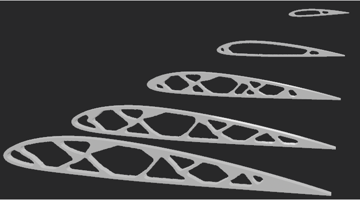
Wing structure generator
Automatic spar and ribs wing structure generation and evaluation pipeline
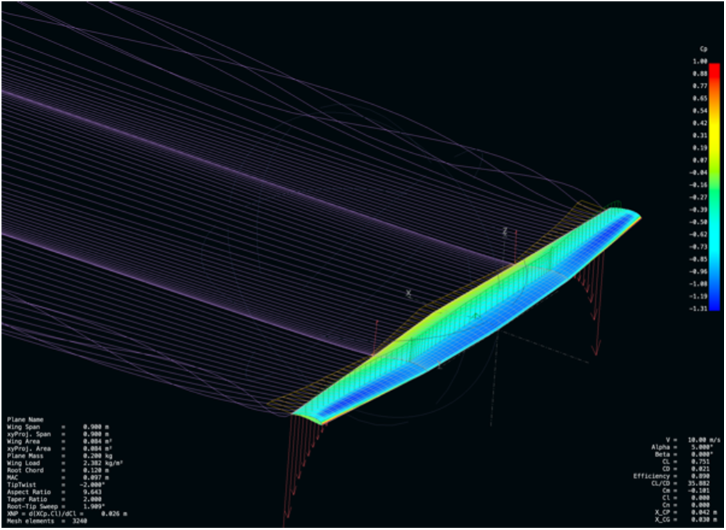
Prion I — Fully FDM-manufactured UAV
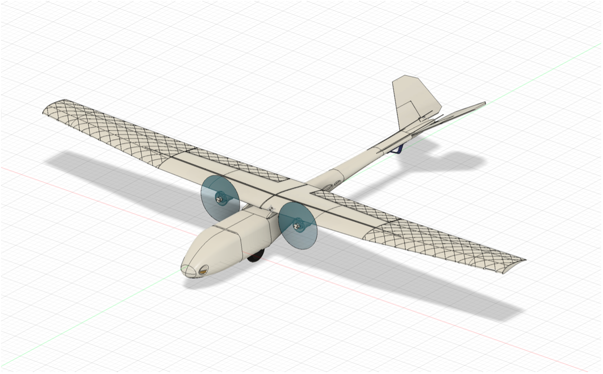
Type: Private project Duration: Feb 2025 – Apr 2025 Role: Sole designer, builder, and pilot Tools: Abaqus, Bambu Studio, FDM manufacturing, Fusion 360, XFLR5
Problem
Assess the feasibility of building a 250 g UAV largely from foaming ASA filament — a material chosen for its low density and resistance to environmental effects like UV light but rarely used in load-bearing aircraft structures.
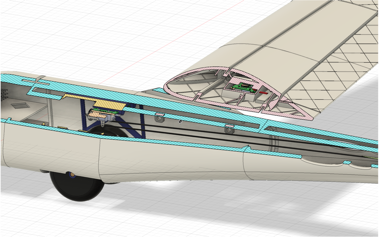
Approach
The foaming nature of the filament drove most design decisions. I used CAD techniques that allowed lightweight parts to be printed without nozzle lifts, producing clean single-wall surfaces. To compensate for weak inter-layer bonding, 1 mm carbon-fiber rods were embedded perpendicular to the layer lines in the monocoque fuselage. The wing planform was selected via vortex-lattice optimization in XFLR5 targeting maximum lift coefficient, and a PETG internal gear carriage was tuned to comply under landing loads, acting as integrated suspension.
Outcome
The resulting UAV came in at 300 g, 50 g above the 250 g target. Aerodynamically, it was capable of remarkably slow flight, though with a strong forward pitching moment from the chosen low-Reynolds, high-lift Selig airfoil — I mitigated this by enlarging the V-tail control surface and adding trim. The wing-mounted motors were strongly undersized, resulting in more of a glider. Next time I’d lean more on the carbon rods to reduce the material needed for the fuselage, and switch to a more traditional single-motor design to cut electronics mass.
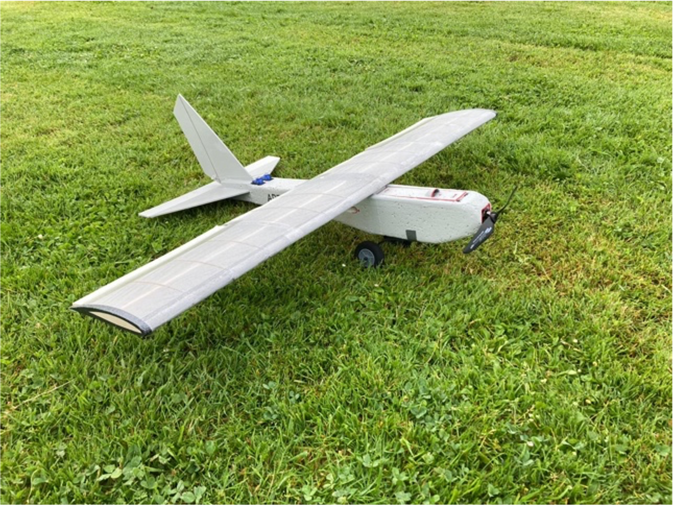
Heron - High aspect ratio, detachable wooden wing
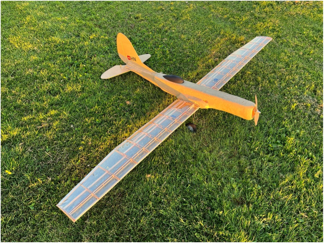
Type: Private project Duration: Jun 2024 – Aug 2024 Role: Sole designer, builder, and pilot Tools: Laser cutting, NX
Problem
Design a low-mounted, high-aspect-ratio wing with a classic spar-and-rib structure out of purely laser-cut pieces. Additionally, the wings should be detachable from the fuselage due to transport limitations.
Approach
To reduce the mass of the aircraft, the fuselage was built largely out of expanded and extruded polystyrene (EPS and XPS). I used the yellow XPS for structurally important areas like the wingbox and potential impact zones due to its higher stiffness and yield strength. The white EPS then played the role of aerodynamic fairing for lower-stress zones, reinforced with aluminum tape in critical areas like the electronics bay. The wing had to be designed around the limitations of laser cutting. The spars were dimensioned with approximate analytical calculations, and the wingbox had an additional plywood structure embedded into it for rigid mounting of the wings.
Outcome
The final aircraft came out at approximately 800 g with a 1.6 m wingspan. Static load tests showed the wing was strong enough for calm flight but would deflect strongly under loads above those experienced in 3 g maneuvers — caused by the combination of high aspect ratio and a very thin tip profile. Unfortunately, I was unable to perform in-flight testing: a torque roll from the oversized motor flipped the aircraft into the ground right after takeoff. If I were to redesign this, I’d artificially thicken the wing-tip airfoils, trading aerodynamic efficiency for structural rigidity. After this flight I started implementing better pre-flight checks and a range of ground tests before any full-power takeoff.
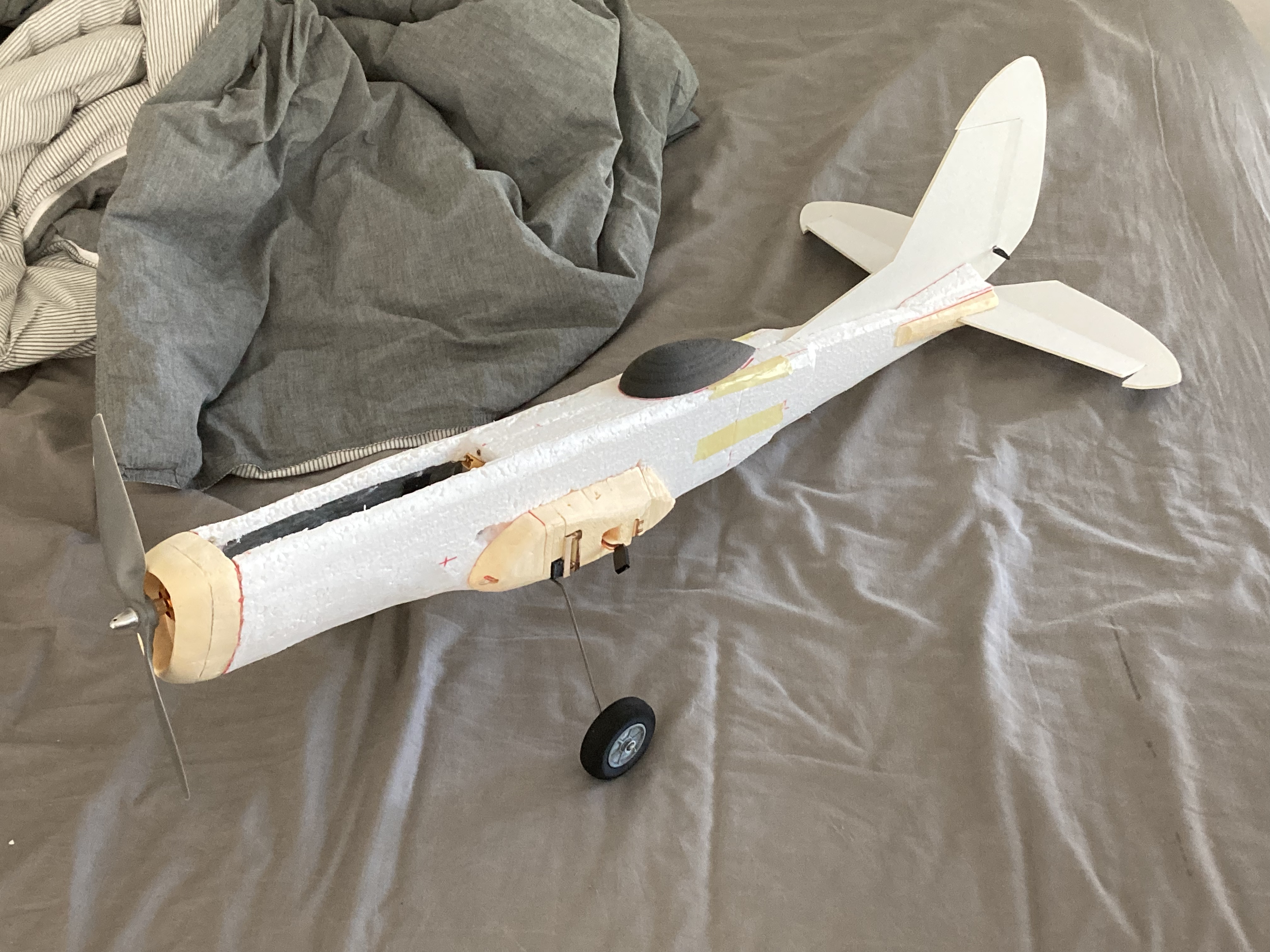
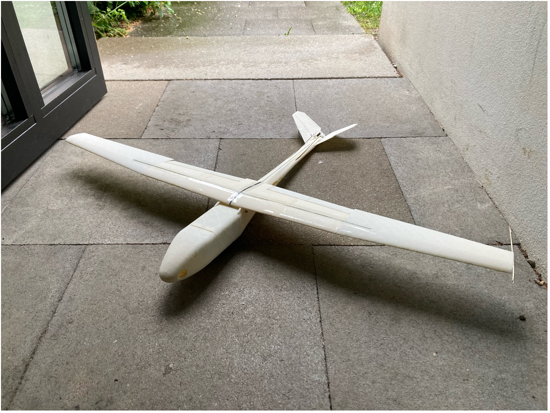
Albatross II - First flying UAV
Type: Private project Duration: Feb 2025 – Apr 2025 Role: Sole designer, builder, and pilot Tools: FDM manufacturing, Laser cutting, NX
Problem
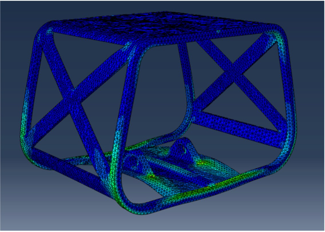
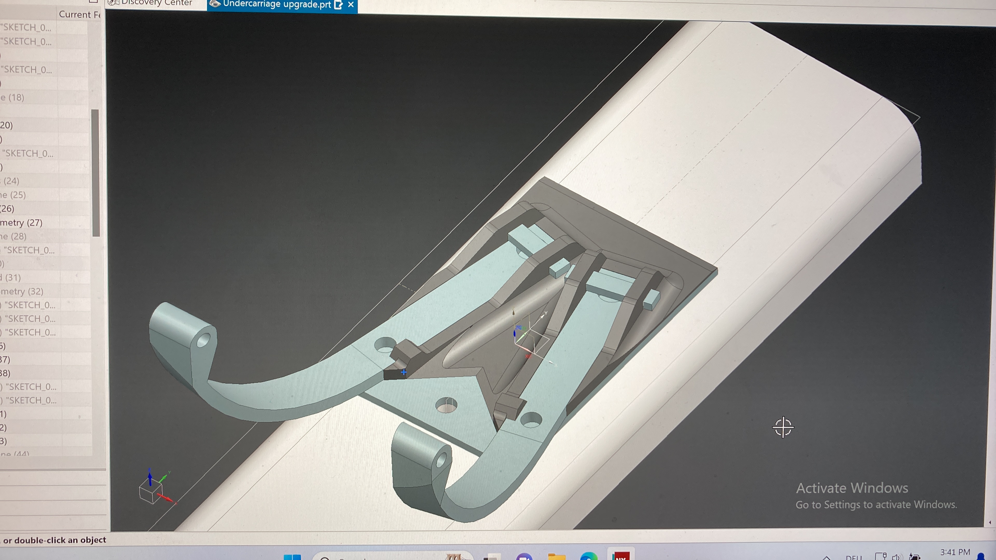
Build a functional UAV with limited resources. After a successful first flight, use it as a testing platform for FDM-manufactured landing-gear suspension designs and stall-delay methods.
Approach
First, I designed a wing-mounting system that allowed me to position the wing freely anywhere along the fuselage length. Then I cut the rough fuselage from expanded polystyrene (EPS) and, with the electronics in place, found its center of gravity. From there I could install the wing hardpoints according to the measured CG positions of both the wing and the fuselage. This process was a direct response to Albatross I, which had failed due to a bad CG estimate that left the aircraft severely tail-heavy. The wing used a balsa main spar with laser-cut and FDM-manufactured ribs in plywood and foaming PLA.
Outcome
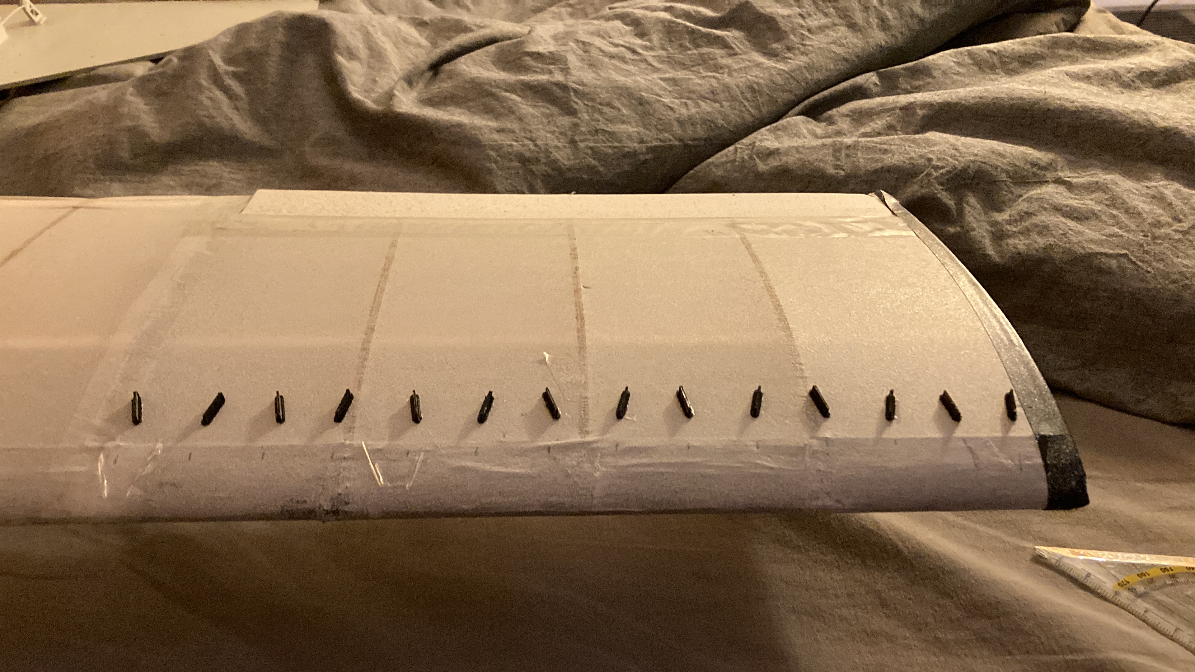
The final aircraft came in at 500 g, 100 g above the 400 g limit, with a 1 m wingspan. It flew well at higher speeds but suffered sudden tip stalls at low airspeed. To mitigate this, a row of vortex generators was installed along the wing tips, resulting in much more predictable stall behavior. After multiple flights, I used this aircraft to test FDM-manufactured landing-gear suspension designs — mostly heavy PETG leaf springs, which gave good suspension behavior but added about 50 g to the aircraft mass.
Desktop CNC Hotwire Cutter
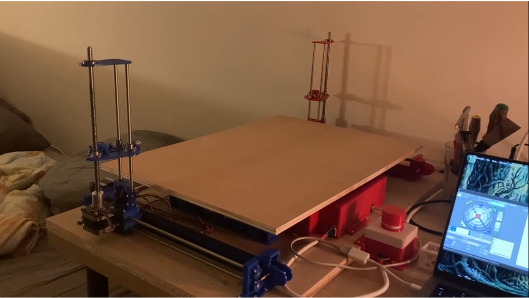
Type: Private project Duration: Mar 2025 – Sep 2025 Role: Sole designer and builder Tools: Arduino, FDM manufacturing, Fusion 360, Marlin, Python
Problem
I wanted to build foam-core wings with fiberglass or carbon-fiber skins, which requires a CNC hotwire cutter accurate enough to produce aerodynamically clean profiles. An additional constraint was that it had to fit on my desk while preserving as much cutting volume as possible.
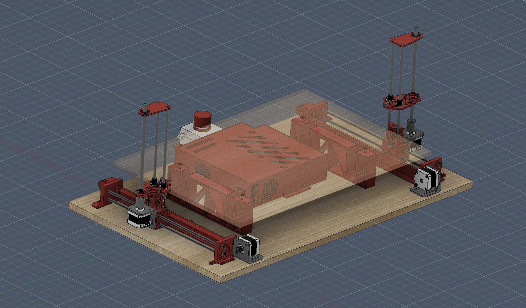
Approach
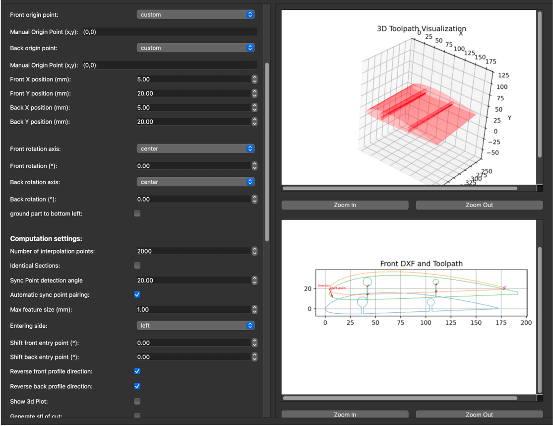
To keep the footprint small, I used a two-layer structure: the bottom plate houses the X-axis motors, gantries, and electronics box, while the foam block sits on an elevated upper plate. Each gantry rides on two cylindrical linear bearings — horizontal axes driven by belts, vertical axes by lead screws. The hotwire is tensioned by a pair of 3D-printed torsion springs on bearings and guided through ceramic nozzles. Electronics run on an Arduino with a RAMPS shield flashed with Marlin. G-code is produced by a custom Python tool that takes two DXFs of the end sections and generates synchronized toolpaths for both gantries, applying kerf and lead/lag corrections as well as toolpath synchronization so the final shape matches the input.
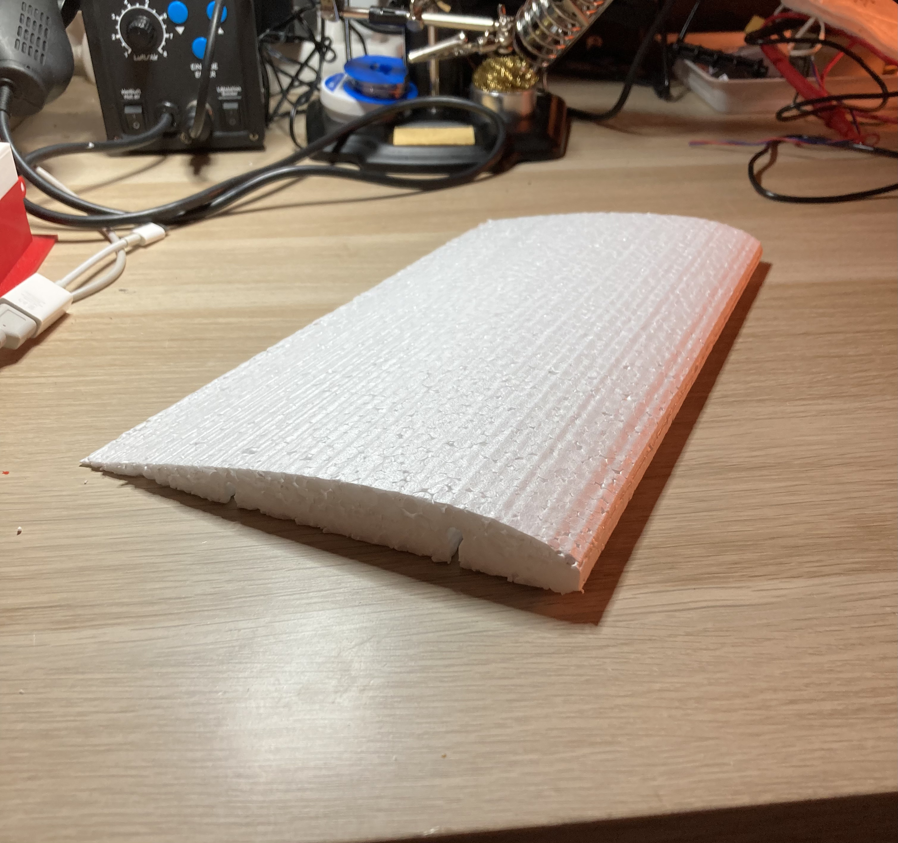
Outcome
Initial tensioning through the narrow ceramic nozzles was unreliable, so I switched to linear springs anchored at each toolhead — this cost a small amount of Y-axis volume but made setup much more repeatable. After tuning feed rates and wire temperature, the cutter produced clean airfoil sections suitable for composite wing cores.
UAV Flight Controller
Type: Private project Duration: Nov 2025 – ongoing Role: Sole designer and builder Tools: Arduino, C++, Fusion 360, PCB design
Problem
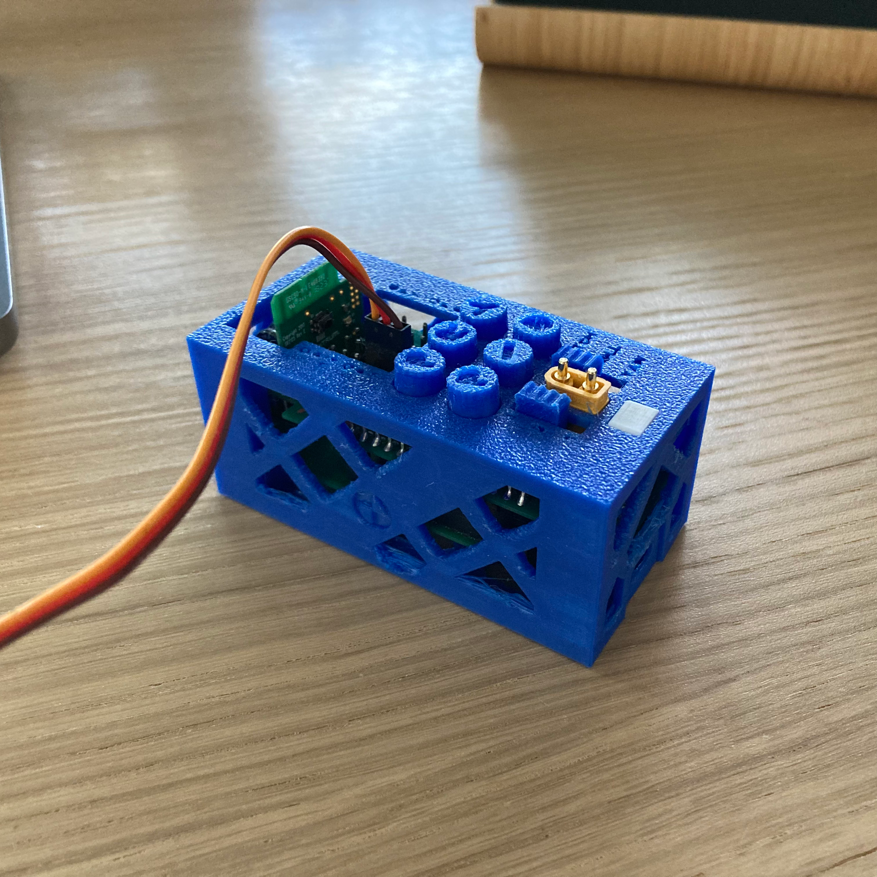
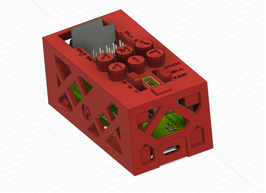
Design a fully self-contained flight controller that extends the capabilities of my receiver with flight stabilization and autotuning, while also supplying power to the servos. It had to be as small and lightweight as possible.
Approach
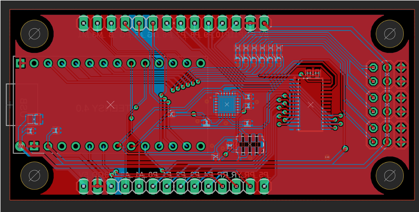
The software runs on a Teensy 4.1 mounted on a custom PCB alongside an IMU and barometer. Sensor fusion gives a continuous estimate of the aircraft’s orientation and body rates, which feed a cascaded PID controller: the inner loop closes on body rates, the middle loop on orientation, and the outer loop provides simple heading and altitude hold. A state-machine failsafe attempts to recover from stalls and other abnormal attitudes.
Outcome
The controller currently handles stabilization in bench tests. Still open: the autotuning routine, which will characterize the airframe by injecting oscillations via a relay element (Åström–Hägglund method), and further work on the failure-detection state machine. I’m also considering collapsing the current two-board sandwich (power on top, signals on bottom) into a single PCB to reduce overall size.
2D incompressible CFD solver

Type: Private project Duration: Dec 2025 – Feb 2026 Role: Sole programmer Tools: Python
Problem
A small side project to learn about computational fluid dynamics. It should be able to simulate 2D, incompressible fluid flows.
Approach
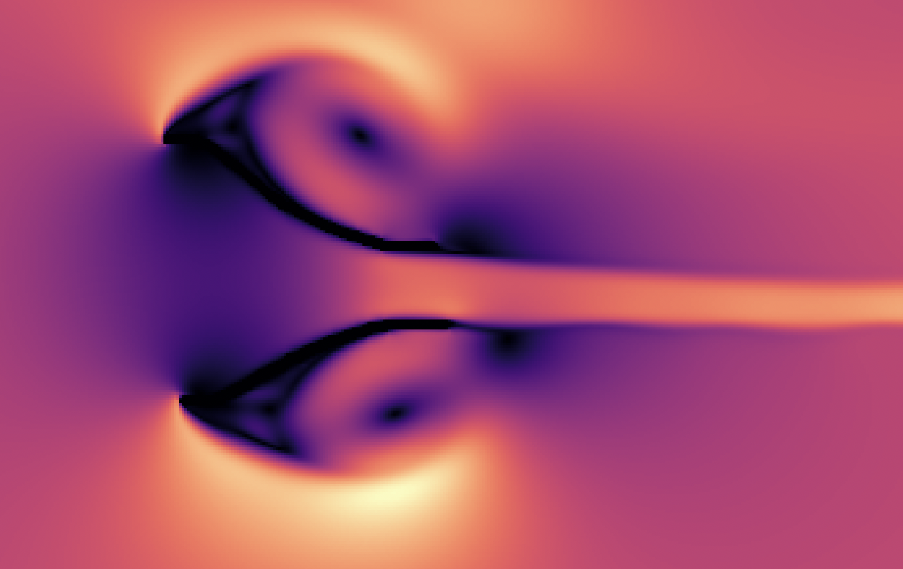
The solver uses a pressure-projection scheme on a staggered MAC grid. Each step first advances the advection and diffusion terms analytically, then recovers incompressibility by solving the resulting Poisson equation for pressure with a multigrid solver. Solid boundaries can be defined analytically, imported from an SVG, or sketched freehand in a small companion drawing tool. The hot paths are compiled with Numba to avoid Python’s per-iteration overhead, and a Spalart–Allmaras one-equation model is available for turbulence.
Outcome
The simulator runs at usable speeds on moderate grids and exposes an analysis script for plotting standard fields (velocity magnitude, curl, pressure) as well as particle advection — the flow animation in the site banner was generated this way. A lighter interactive version runs live on a reduced grid. Spalart–Allmaras works but is inaccurate on the coarse meshes this implementation can handle in reasonable time; finer grids become computationally expensive, which would be the first target for future optimization work.

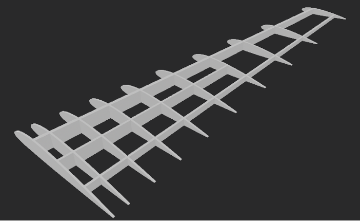
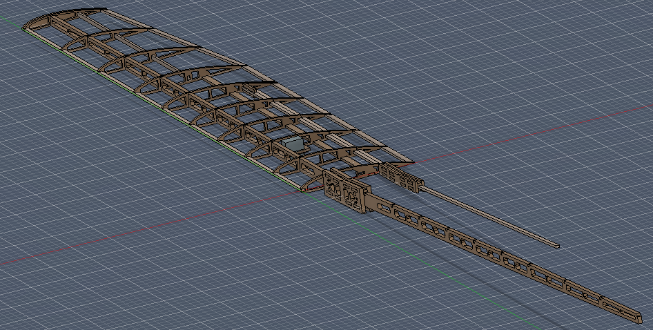
Automatic Wing Structure Generator
Type: Thesis project Duration: Feb 2026 – Jun 2026 (ongoing) Role: Sole programmer for structure generation and analysis Tools: Python
Problem
This thesis is part of a larger effort to build a pipeline that lets a machine-learning model generate a fully manufacturable, flyable UAV from a requirements PDF. Before I joined, the pipeline could generate optimized STL models of the external UAV shape; my job is to lay the groundwork for generating and evaluating internal wing structures from that external geometry.
Approach
The tool first generates a rough spar-and-rib structure from a small parameter set. A custom FEA solver then analyses this rough structure and returns quick metrics (mass/stress ratio, maximum stress, etc.) so the user can judge viability before spending any optimization time. Once the rough layout looks reasonable, a custom topology-optimization routine refines each rib individually, minimizing compliance at a target volume fraction.
Outcome
The scaffolding for the full program is in place. Remaining work is mostly on the structure generator — handling spar/rib intersections and enforcing assemblability — plus refining the FE solver for spars and adding a spar-level optimization pass.